Monitoring the Nissan Leaf using an ELM327 diagnostic tool
An introduction to reading the Car-CAN bus of the Nissan Leaf using an ELM327 compatible diagnostic tool.
Requirements
ELM327 compatible OBD-II diagnostic tool.
Terminal application running on a mobile or laptop.
Nissan Leaf.
The examples in this tutorial use a Vgate Wi-Fi diagnostic tool and Serial Wi-Fi Terminal for Android by Kai Morich. The same developer has also written Serial USB Terminal and Serial Bluetooth Terminal for Android.
The vehicle used in this tutorial is:
- Vehicle:
Nissan Leaf
- Year:
2013
- Model:
AZE0-0 G-spec
- CAN protocol:
ISO 15765‑4 (CAN 11/500)
ELM327 OBD-II diagnostic tool
ELM327 diagnostic tools are available supporting either wireless or wired communication protocols. Wireless communication protocols include:
BT
BTL
Wi-Fi
Wi-Fi diagnostic tools have the disadvantage that while in use your mobile or laptop is unable to connect to any other Wi-Fi network.
The most common wired communication protocol is USB.
Note
Unfortunately the market is flooded with counterfeit ELM327 microcontrollers which have made their way into inexpensive diagnostic tools. Often these devices do not fully support the ELM327 specification [JRPollock17].
Genuine ELM327 microcontrollers are supplied by ELM Electronics Inc. who recommend seeking the assurance from the device vendor that they use genuine ELM parts [elm20].
Terminal application
Select a terminal application that can be configured to connect to your diagnostic tool via the appropriate communication protocol.
Nissan Leaf
The Leaf has three CAN buses commonly referred to as: Car-CAN, EV-CAN, and AV-CAN. The diagnostic connector CAN pin assignments are depicted in Figure 3 and listed in Table 8. The CAN protocol used in the Car-CAN bus of the Leaf is ISO 15765-4 CAN (11-bit ID, 500 kBd) which is often abbreviated to “ISO 15765‑4 (CAN 11/500).”

Figure 3 Nissan Leaf ISO 15031-3 diagnostic connector pin assignment (mating-end view)
CAN bus |
Diagnostic connector pins |
|
|---|---|---|
CAN high |
CAN low |
|
Car-CAN |
|
|
EV-CAN |
|
|
AV-CAN |
|
|
 6
6 14
14 12
12 13
13 3
3 11
11Standard OBD-II diagnostic tools connect to the Car-CAN bus on pins 6 and 14.
The Leaf does not support any the standard PIDs which are mandated for internal combustion engine vehicles. This is despite having a OBD-II diagnostic connector in compliance with ISO 15031-3, and the CAN protocols complying with ISO 15765‑4.
In addition to the Leaf not supporting standard PIDs there can be PID variations between Leaf models.
Set up
Set up involves connecting the diagnostic tool to the vehicle and configuring the terminal application which runs on your mobile or laptop.
Warning
Using a poor quality diagnostic tool may cause the vehicle to behave unexpectedly.
Connect the diagnostic tool
Insert the diagnostic tool into the vehicle’s OBD-II diagnostic connector – which is found beneath the steering column. Then power-on the vehicle to activate the Car-CAN bus.
Configure the terminal application
Configuration of the terminal application depends on the communication protocol supported by your diagnostic tool and the terminal software being used.
Wi-Fi:
Connect to the diagnostic tool as you would connect to a Wi-Fi access point.
Configure the terminal application with the host and port of the diagnostic tool according to the user guide. Common configuration is:
- Host:
192.168.0.10
- Port:
35000
- Protocol:
Raw
Bluetooth and Bluetooth Low Energy:
Pair the diagnostic tool with your mobile or laptop.
Once paired the tool is available for selection in the terminal application.
Diagnostic tool commands
The ELM327 is instructed by sending a series of AT commands from the terminal application.
AT commands
Commands used in this tutorial are listed in table Table 9. The complete ELM327 command set can be found in the ELM327 specification.
Command |
Description |
|---|---|
ATZ |
reset all |
ATI |
print the ELM327 firmware version ID |
ATL1 |
line feed on |
ATH1 |
header control on |
ATS1 |
print spaces on |
ATAL |
allow long messages |
ATSP6 |
set CAN protocol to ISO 15765-4 CAN (11/500) |
ATCRA 358 |
filter message with PID 0x358 |
ATMA |
monitor all |
Read turn signal status
In Listing 5 the status of the vehicle’s turn
signal is read. Commands on lines 1 to 7 initialise the ELM327. Command
ATCRA 358 on line 8 filters messages with the PID 0x358.
 1> ATZ
 2> ATI
 3> ATL1
 4> ATH1
 5> ATS1
 6> ATAL
 7> ATSP6
 8> ATCRA 358
 9> ATMA
10358 00 08 80 00 00 00 00 00
11358 00 08 80 00 00 00 00 00
12358 00 08 80 00 00 00 00 00
13358 00 08 82 00 00 00 00 00
14358 00 08 82 00 00 00 00 00
15358 00 08 82 00 00 00 00 00
16358 00 08 80 00 00 00 00 00
17358 00 08 80 00 00 00 00 00
18358 00 08 80 00 00 00 00 00
19358 00 08 84 00 00 00 00 00
20358 00 08 84 00 00 00 00 00
21358 00 08 84 00 00 00 00 00
ELM327 session 0x358 turn signal status
The output is displayed following the command ATMA on lines 10 to 21. As
the turn signal leaver is operated the third byte changes correspondingly:
- off:
8016 = 100000002
- left signal:
8216 = 100000102
- right signal:
8416 = 100001002
A screenshot of the serial terminal session prior to executing ATMA is
shown in Figure 4.
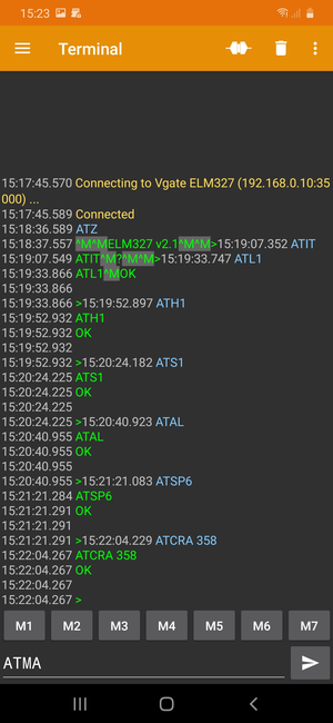
Figure 4 ELM327 serial terminal session on an Android-powered device [KaiMorich]
See also
- Diagnostic connector
Detailed description of the Leaf OBD-II diagnostic connector.
- 358 turn signal
PID 0x358 Turn signal.